Mechtron 3TB4: Embedded Systems Design II
Lab 1
Control of a Stepper Motor
Reports Due:
Part 1: No later than 11:31 hrs on Monday Jan 18, 2010, at the start of class in BSB/108.
Part 2: Week Starting Jan 25, 2010, at the beginning of your next tutorial sessions (to be handed over to your TA in hardcopy or available in PDF in your subversion repository).
Goals:
-
Learn about stepper motor basics and how to control a stepper motor using a microcontroller
in full/half step mode and clockwise/counterclockwise direction, while controlling the speed of rotation
- Learn how to use AVR to interface a physical device.
- Practice the use of AVR timer using interrupts and polling
Note: This lab consists of three (3) activities. Marks allocated to each are indicated in square brackets.
Before you go for your lab session, please read relevant portions of the following documents at your own convenient time, in addition to the class notes:
Equipment Arrangement:
The stepper motor used in the lab is a 26M048B1B from Thomson Airpax Mechatronics, which is a 48 step motor.
To drive the motor, any of the sequences of
signals described in class can be used.
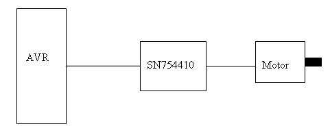
To drive a stepper motor, a signal conditioning stage is needed. In the lab we will use a SN754410NE. In addition, you will use 8
diodes to protect the control circuitry from voltage spikes that would otherwise be produced by the windings (see p. 6 of the SN754410 datasheet).
A sequence of signals is generated through software using timer 0 of the AVR. This sequence is
used to control appropriate switches in the H-bridge and the output of the H-bridge is connected to
the four terminals of the motor. A block diagram of the equipment arrangement is shown in figure 1.
Pre-lab [30 marks]
The following activities must be completed by each student independently and submitted as part 1 of the lab report
at the start of class on Monday Jan 18, 2010. Late submissions will not be accepted.
-
Calculate the angular resolution of the given motor, which makes 48 steps per revolution.
- In this lab we will use the stepper motor to implement an unusual clock.
The motor’s shaft will be connected to a dial of the clock. Hence, we would like the motor to complete
one full revolution in a very specific amount of time. The amount of time (in seconds) will be equal
to the last two digits of your student number. To make the testing times reasonable and fairer across
the class, you can adjust this number if it is very low or very high. Please use the following scheme
to do that:
- If the last two digits of your student number are less than 33, add 33 to it and use that number. E.g. if your student number is 654321, last two digits are 21, which is lower than 33. Then you add 33 to get 54 seconds, which is the period you should use.
- If the last two digits are between 33 and 66 (inclusive), use the last two digits unchanged. E.g. if your student number is 123456, you should simply use 56 seconds for the period.
- If the last two digits are greater than 66, subtract 33 from it and use that number. E.g. if your student number is 56789, last two digits are 89, which is greater than 66. Then you subtract 33 to get 56 seconds, which is the period you should use.
- Determine time period between two steps of the stepper motor used in the lab required for the motor to complete one revolution per period calculated in step 2 for:
- Half-stepping sequence
- Full-stepping sequence
- In the lab you will use Timer 0 of ATMega324P to measure time periods. Assuming you will use the 16 MHz clock available on the boards, calculate the counter reload number that will enable you to measure the period of time calculated in steps 3a and 3b.
- Write AVR code that uses Timer 0 and the stepper motor to implement the clock that completes one revolution per period calculated in step 2. Implement this in the following two ways:
- Use polling and full-stepping sequence
- Use timer interrupts and half-stepping sequence
Make sure that the direction of the motor movement (clockwise/counter-clockwise) can be easily changed in your program.
- Read the documentation for the SN754410NE. Draw a schematic of how you will connect AVR, SN754410NE, diodes, and the motor
In the Lab [50 marks]
IMPORTANT NOTE: IN ORDER TO AVOID EXPENSIVE DAMAGE, DO NOT TURN
ON YOUR MOTOR WITHOUT APPROVAL FROM A TA. IF YOU DO NOT GET APPROVAL
FROM THE TA AT THE APPROPRIATE POINTS, YOU MAY BE ASSIGNED
A ZERO FOR THE LAB.
Version Control
Login to the PC at your lab station. Open a file browser and create a directory called Labs. Right click on it and select the TortoiseSVN Checkout command to check out your Lab Group’s working directory. It should be a URL of the form https://websvn.mcmaster.ca/mt3tb4/groupX where X is your group’s number. (See the TA if you are unsure of your group number.)
You will have different solutions from your pre-lab (pre-labs should be completed individually). In the lab you need to demonstrate only one working program/circuit per group.
-
Using the equipment available in the lab, determine which wires on the motor correspond to the 2 windings.
- Connect the motor, AVR and SN754410NE according to the schematic you developed in the pre-lab. You may want to add some kind of marker to the motor shaft, to easily observe its movement. You can use a piece of tape wrapped around the shaft for this.
- Perform any experiments required to answer the questions in the lab report section below.
- Test the behaviour of your circuit and demonstrate its operation to one of the TAs. The TA may ask you to demonstrate different modes of operation (polling/interrupt version, clockwise/counter-clockwise rotation).
- (Bonus: This part will NOT be marked)
Change your program so that the motor speed can be changed by pressing push buttons on the development board
Lab Report [20 marks]
The following report should be done as joint work in the lab group.
Describe what you did in this lab, include the code used and answer the following questions:
-
How does the behaviour of the stepper change when you exchange the two sides of one winding (e.g. exchange A1 and A2), without changing the program.
- How does the behaviour of the stepper change when you exchange the two winding (i.e. exchange A1 and A2 with B1 and B2)
- Which registers did you have to set to enable timer interrupts? What values did you write into them and why?
This document was translated from LATEX by
HEVEA.