SE 2DA4 Frequently Asked Questions
- How do I get Quartus Prime Software for home use?
- What edition of Quartus is used in our labs?
- How do I set up the license manager in our labs?
- How do I setup the license manager from home?
- How do I create a project and program the FPGA on DE1-SoC board?
- Can I leave the FPGA plugged in 24/7?
- Why doesn't the simulation of my D flip-flop/State Machine work?
- How to power on the DE1-SoC board?
- What will be the signals or logic levels for the toggle switches on DE1-SoC boards?
- What will be the signals or logic levels for the push buttons or KEYs on DE1-SoC boards?
- What kind of signal is required to turn the LEDs on or off?
- How to make the 7-Segment display light up?
- Is there other good reading material for DE1-SoC/Quartus beginners?
- How do I access the Department computer network?
- How do I access Quartus remotely?
Answers to Questions
"How do I get Quartus Prime Software for home use? "
Quartus can be downloaded from Intel's website:
- Go to https://www.intel.com/
- Under the "PRODUCTS" tab, find the "FPGAs & Programmable Devices" category.
- Select "Quartus Development Software & Tools," then select "FPGA Design & Simulation Tools".
- On the same page, find and select "Quartus Prime Design Software".
- Go to the "Download" tab to download the appropriate edition and version for your operating system.
From Intel's website, you can download either the Standard Edition or the Lite Edition of Quartus Prime for Windows or Linux to install on your own PC/laptop.
Quartus Prime Lite Edition is a free, no-license-required version of Quartus. Students can use it to compile their projects and download the projects to their DE1-SoC boards, if they have their own DE1-SoC boards at home.
The Quartus Prime Lite Edition can be used without network access, but it does not have all the features.
We recommended you to download and install Quartus Prime Standard Edition Version 23.1.1, as this is the version and the edition of Quartus Prime installed on our lab computers. When downloading and installing, please make sure the following three components are available. They are:
- "Quartus Prime (include NIOS V EDS)",
- Questa-Intel FPGA Edition (comes with Quartus Prime). This is the EDA tool for simulation, and
- "Cyclone V device support". Because our lab will use DE1-SoC boards, which belong to the Cyclone V family.
Quartus Prime Standard Edition and Questa-Intel require a license to run. Our department has a license file, which is at 27000@alteralm.cas.mcmaster.ca . You need to use VPN to access our department license server if you are off campus.
"What edition of Quartus is used in our labs?"
The Quartus Prime Standard Edition is used in our labs. Quartus Prime Standard Edition supports more hardware and compiles faster than the Quartus free edition. It has more support from Altera and has more functions. A license is required to use this edition, although there is a 30 days trial version available.
"How do I set up the license manager in our labs?"
License is required to be set up when the user starts Quartus for the first time. Our labs use a license file. The license file name is: 27000@alteralm.cas.mcmaster.ca.
Steps to specify a license file for Quartus Prime in the lab:
1.) Choose the option to use a valid license file to set up the license
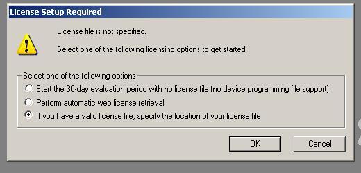
2. ) Provide the license file name:
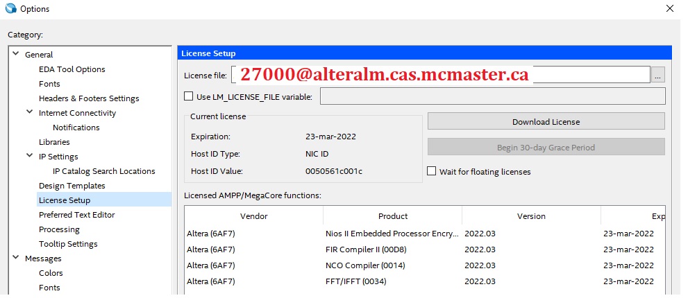
In case you need to set up a license in the middle of using Quartus Prime. The steps are as follows:
Under Tools | License Setup, type in "27000@alteralm.cas.mcmaster.ca" for the license file. NOTE: Quartus might still complain about the license if you try to compile or simulate your projects. If that happens, just execute the compile/execute command again and it should work fine. Check with the TAs to make sure the license file name has not been changed.Questa-Intel also needs to set up a System Environment Variable "LM_LICENSE_FILE" and set its value to a valid license file, which is "27000@alteralm.cas.mcmaster.ca" in our case. The steps are as follows:
- On Windows taskbar, right click the Windows icon and select "System".
- In the opened window, under the "Related Setting" section, click "Advanced system settings".
- In the opened "System Properties" window, click the tab "Advanced", then click the button "Environment Variables".
- Under the section "System Variables", click the button "New..." to create a new environment variable.
- In the "New System Variable" window, input "LM_LICENSE_FILE" as the variable name, and "27000@AlteraLM.cas.mcmaster.ca" as the variable value.
" How do I set up the license manager from home?"
Download Cisco AnyConnect from: https://uts.mcmaster.ca/services/computers-printers-and-software/virtual-private-networking/
Follow the instructions in the section of "CREATE A CONNECTION" at: https://uts.mcmaster.ca/services/computers-printers-and-software/virtual-private-networking/
Basically, you need to enter "sslvpn.mcmaster.ca" for the server name.
Then when promoted, you need to provide your MAC ID (username and password).
The rest of the steps are the same as in the lab.
"How do I create a project and program the FPGA on DE1-SoC board?"
The major steps to create a project and to program the FPGA on DE1-SoC boards are:
- Start Quartus Prime.
- Set up a license, if it is required.
- Create a new project by File | New, then select "New Quartus Prime Project". Or by File | New Project Wizard. If you have a project ready, then open it by File | Open Project.
- Specify a working directory, a project name, and a name of the top-level design entry for the project.
"The project must have a name, which is usually the same as the top level design entity..."
NOTE: Please avoid saving the project on the desktop in the lab computers because the path to the working directory will contain spaces, and this may give troubles to Quartus to compile and to download the program to DE1-SoC. Save on your Z: drive, which is actually your file space on our department file server, or save in other folders instead.
- For Family and Device Settings: The DE1-SoC board belongs to the "Cyclone V" family, the FPGA is called "5CSEMA5F31C6".
- Add new files to the project by File | New, then select the types of Design Files such as VHDL, AHDL, or Verilog HDL files.
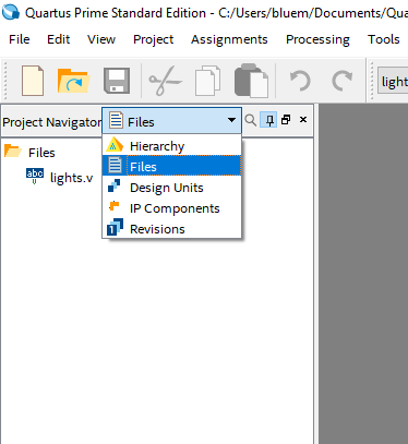
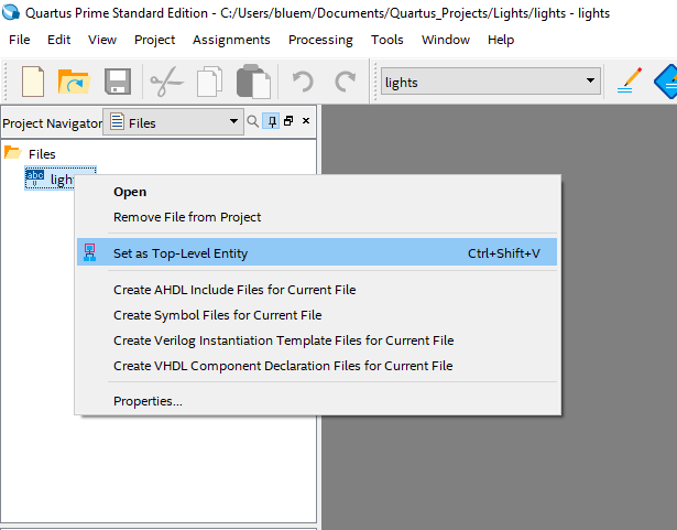
- Remember to set a project file as the Top-Level Entity file by right-clicking the file name in the Project navigator window while the "Files" tab is selected, then select "Set as Top-Level Entity" in the context menu. The Top-Level Entity is the root of a project design hierarchy. It is like the main function in C program.
- If the project needs to use the buttons, switches, LEDs or other actual components on the DE1-SoC boards, users need to complete the pin assignment steps. A convenient way to use the actual components on DE1-SoC boards is as follows:
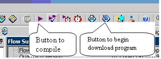
- Compile the project by Processing | Start Compilation, or by clicking the icon on the toolbar.
- Prepare the hardware to download the program to DE1-SoC board. This includes: powering on the DE1-SoC board, connecting the USB/Blaster cable, and setting the switch 10 properly.
- Download the project to DE1-SoC board by Tools | Programmer, or by clicking the icon on the Quartus toolbar. Depending on your system setup, you may need the following steps to program the FPGA on DE1-SoC boards:
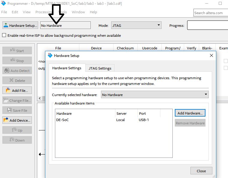
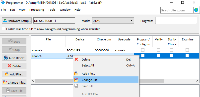
- If the Programmer window shows "No Hardware" for hardware setup, you need to click the button "Hardware Setup", then in the opened Hardware Setup window, double click "DE-SoC" and then close the window.
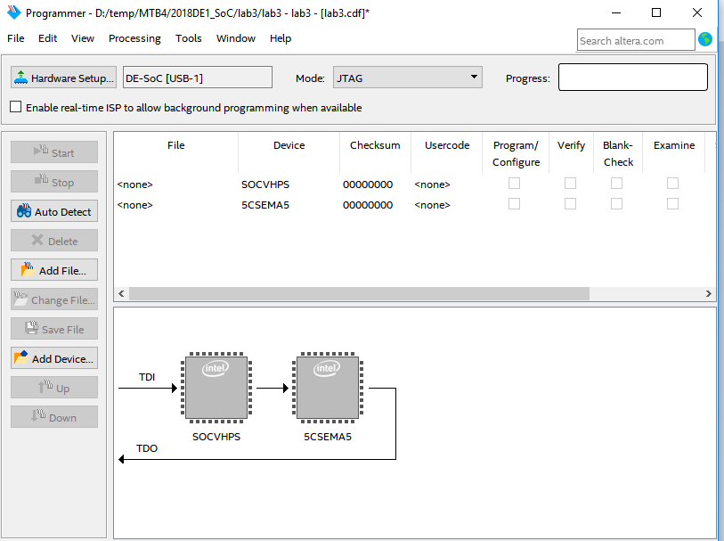
- Now the Programmer window should look like the following image:
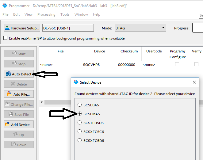
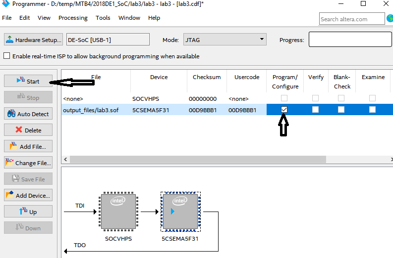
- In the lower part of your Programmer window, if the devices, "SOCVHPS" and "5CSEMA5", are not configured in the same way as shown in the above figure, you can delete all the devices, then click the "Auto Detect" button, and then select device "5CSEMA5".
- In the upper part of the Programmer window, RIGHT click the line for device "5CVSEMA5" and select "Change File", and then select the compile project .sof file.
- After the output file is changed, tick the check box in the "Program/Configure" column, and then click the button "Start" on the left side to program the FPGA.
In the project, use the signal names in the same way as specified in DE1-SoC user manual. For example: for the 10 toggle switches the signal names should be : SW[0], SW[1]....SW[9], then assign pins by simply importing a pin assignment file, DE1_SoC.qsf which is provided by Altera and can be found on our course web page and in your provided lab materials.
To import a pin assignment file, click Assignment | import assignment, then select the .qsf file.
"Why doesn't the simulation of my D flip-flop/State Machine work?"
Make sure that you are doing a timing simulation, and not a functional simulation.
Sequential circuits have feedback which relies on gate delay to work correctly.
Timing simulation includes gate delays, but functional simulation treats the circuit as ideal gates with zero delays!
"How to power on the DE1-SoC board?"
The red push button on the left side of the board is the power button.
"What will be the signals or logic levels for the toggle switches on DE1-SoC boards?"
For the 10 toggle switches: When a switch is in the DOWN position (closest to the edge of the board) it provides a low logic level (0 volts) to the FPGA, and when the switch is in the UP position it provides a high logic level (3.3 volts)."What will be the signals or logic levels for the push buttons or KEYs on DE1-SoC boards?"
For the four push buttons: Each button provides a high logic level (3.3 volts) when it is not pressed, and provides a low logic level (0 volts) when depressed."What kind of signal is required to turn the LEDs on or off?"
For the 10 user red LEDs on DE1-SoC boards, driving the associated pin for an LED to high logic level turns the LED on, and driving the pin low turns it off."Is there other good reading material for DE1-SoC/Quartus beginners?"
- DE1-SoC user manual: DE1-SoC_User_manual.pdf
- Quartus Prime Introduction Using Verilog Designs: Quartus_Std_Introduction_Verilog.pdf
- Introduction to Simulation of Verilog Designs: Waveform_Simulation.pdf
"How do I access the Department computer network?"
This is a separate network from the one you use to access mail and Mosaic, and requires a separate password.
If you have troubles to access the department computers in the lab, this may be why.
The easiest way to set the CAS network password to be the same as your mcmaster.ca passwd (email, etc) is to use the link below.
https://www.cas.mcmaster.ca/macidYou enter your macid and passwd, and it will set your cas passwd (the user id for CAS should already be set to the same as your macid) to the same as your macid passwd.
It is possible to access the Quartus software remotely on the department network.
If you have Quartus installed and working on your own computer, that will give you the best behavior/performance by far.
If you are having issues, or using Mac OS X, it is possible to access the department computers remotely.
The department has allocated several virtual Windows machines with Quartus installed for SE 2DA4. Of that, most are being used for the in-person lab, but the rest are available for remote access.
Note: before accessing web website below, you first need to be on campus or using a VPN (See 2DA4 FAQ about using a VPN).
See here for details: https://www.cas.mcmaster.ca/support/index.php/Virtual_Desktop
They are accessed using vmWare Horizon client (says there is a MacOS X client) or via a web browser (I'd recommend the client).
Log in VirtualDesktop.cas.mcmaster.ca using your CAS network userid and password (see earlier post), then select the virtual machine pool for SE2DA4 to log in to a machine.
In the program menu, you can find Quartus under the "Intel FPGA" sub-menu.